Requirements for railway transformers
Static rail vehicle inverter transformers operate under harsh conditions. Traction power supply, combined with the expectation of extreme reliability, defines the parameters and stringent requirements for the transformer insulation system. Climatic conditions and mechanical influences are additional constraints that affect the construction solutions adopted and the materials used.
The technical standard EN 60310 defines the general requirements for transformers and chokes used in rolling stock. From the point of view of transformers, the requirements of the PN-EN 50124-1 standard concerning the coordination of insulation according to overvoltage class (OVx), which determines the expected overvoltage exposure of insulation, deserve special attention. The concept of the soiling zone (PDx) is introduced, which has an impact on insulation clearances and the technological solutions used. EN 600721 classifies groups of environmental factors and their intensity at the location of transformers, taking into account impacts of climatic, biological, chemical and mechanical nature.
Mechanical impacts are an extremely important aspect in electro-mobile applications. Methods for testing the immunity of transformers to vibrations generated during vehicle motion and transmitted to equipment installed on board are defined in EN 61373. The document specifies the frequencies and amplitudes of vibrations acting in different planes on the transformer depending on where the equipment is installed on the rail vehicle.
Transformers and chokes in mobile railway applications must meet the stringent requirements of all the standards in question. The increased technical requirements make them non-standard, high-tech devices.
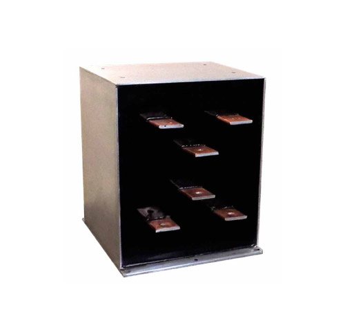
Figure 1. Three-winding electromobility inverter transformer for PD4 contamination zones.
Design and optimisation of structures
The main optimisation objective of the work on railway transformer design is to achieve the lowest possible component weight while maintaining electrical, climatic and mechanical performance.
During development work on transformer design for railway applications, a number of
computational simulations were performed for core designs made of different magnetic materials. The simulations used the loss algorithm and temperature model used in the transformer design software from RALE Engineering GmbH [6].
The low frequencies of the supply voltage (approx. 1 kHz) make it possible to consider using isotropic, anisotropic sheets and amorphous magnetics for the construction of low-loss transformer cores (Table 3).
Achieving the expected level of power loss in a core made of transformer sheets is possible by limiting the magnetic induction in the core. However, this results in an unintended large increase in core mass, which is one of the most important constraints. In this situation, materials with lower losses are used. Amorphous magnets, due to the small thickness of their sheets in the case of transformers, show much lower losses from eddy currents.
The low dissipation of the amorphous material allows for adequate core losses while maintaining an acceptable device weight. However, a large magnetostriction coefficient is a problem with this group of materials. This creates an intensive sound field around the running transformer, which is an unacceptable effect from the point of view of the intended application.
The non-standard approach to the enclosure concept makes it possible to eliminate areas of increased generation or accumulation of losses causing excessive temperature increases (Figure 2).
In high-frequency applications (Table 4) we get much smaller transformer weights and dimensions. Cores in this frequency range are built from ferrites or nanocrystalline magnetics. The windings, due to high additional losses, are constructed exclusively from face-type copper conductors.
Magnetic materials
The magnetic materials used for power transformer cores in electromobility applications include soft ferrites, low-loss generator and transformer sheets, and amorphous and nanocrystalline alloys in the form of thin strip cores. The magnetic core material is selected to suit the specific power and load conditions of the transformer, the size and intended use of the device, taking into account the parameters of the magnetics, such as dissipation, magnetic saturation induction or magnetostriction.
The formation of satisfactory properties of alloys is possible through modifications of their chemical composition, crystal structure, plastic and thermomagnetic processing. In the case of low-silicon and high-silicon sheets, with an increase in silicon content, their magnetic permeability increases, losses in iron during remagnetisation decrease, leading to a reduction in eddy current losses as the resistivity of the alloy increases. The coercive intensity also decreases, thereby reducing the hysteresis loss and magnetostriction coefficient [1]. However, the decrease in magnetic saturation induction is unfavourable from an application point of view.
Iron-based amorphous alloys are characterised by significantly higher magnetic permeability values compared to silicon sheets, with a small coercive field and lower loss. An important property of amorphous materials, from the point of view of industrial applications, is the small increase in total loss per unit mass in the elevated frequency range. These alloys are obtained in the form of thin strips by the technique of rapid cooling of the molten material on a rotating roller [3].
Very good so-called soft magnetic properties of amorphous alloys are related to their structure, in which there is no long-range ordering of atoms, resulting in the disappearance of magnetocrystalline anisotropy, grain boundaries and other structural defects typical for polycrystalline materials [4]. An
unquestionable advantage of this type of material is that it is easy to improve its properties by changing its chemical composition and annealing under appropriate conditions. Striving to improve the efficiency of energy conversion and extend the temperature or frequency ranges of devices has led to the creation of nanocrystalline materials. They are obtained by partial crystallisation of amorphous alloys in an optimisation annealing process. This process leads to crystallites less than 100 nm in diameter, embedded in an amorphous matrix. This group of alloys includes well-known materials such as FINEMET, NANOPERM and HITPERM. These materials have a high magnetic permeability value of the order of 106, a saturation induction (depending on the chemical composition of the alloy) in the range of 1.2 – 1.9 T, a near-zero magnetostriction (λs of the order of 10-6), a small coercive field (HC < 1A/m) and core losses of the order of 0.1 W/kg (at 50 Hz) [5].
Ferrite materials are often used in high frequency applications due to their relatively low price and availability. They are characterised by a low saturation induction of about 0.4 T, low magnetic permeability and lower loss compared to other core materials.
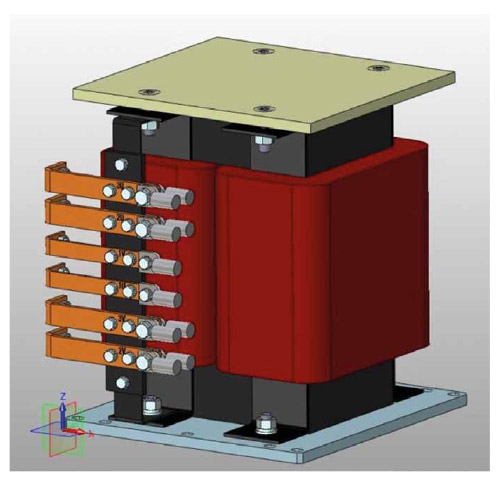
Figure 2. Electromobility converter transformer without housing
Download PDF
M. Łukiewski, A. Łukiewska – Napędy i Sterowanie 12/2018