Core chokes operating in power electronic circuits are a significant source of power loss. Losses in inductive components are amplified by the effects of higher voltage and current harmonics on the core and windings. This paper discusses the basic issues of power losses in the windings of inductive components.
Choke windings
Core chokes operating in power electronic circuits are a significant source of power loss. Losses in inductive components are amplified by the effects of higher voltage and current harmonics on the core and windings. This paper discusses the basic issues of power losses in the windings of inductive elements with so-called soft magnetic properties. Similarly diverse in design and technology are the choke windings. The conductor materials commonly used for choke windings are copper and aluminium, in the form of bales, round and profile conductors and face-type conductors. The windings of chokes operating in high power circuits of power electronic circuits are most often constructed from thin copper or aluminium sheets and parallel bundles of profile wires.
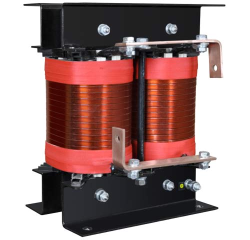
Fig.1 Single-phase core choke.
Proximity effect
The windings of high power chokes are constructed from bundles of parallel flat profile wires or sheets, insulated and wound with high tension. In the case of parallel current paths which are directly adjacent to each other, we observe the interaction of the magnetic fields of the individual conductors called the proximity effect. As a result of the interaction of semi- magnetic variables, eddy currents cause an increase in power losses in the conductors in addition to the losses resulting from the skin effect [2,3,5].
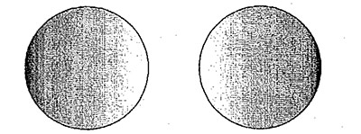
Fig.4 Illustration of current distribution in parallel conductors when currents flow in the same direction. [2]
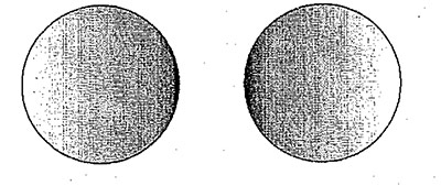
Fig.5 Illustration of current distribution in parallel conductors when currents flow in the opposite direction. [2]
For round conductors of d diameter, arranged at a distance s from each other, with the same direction of current flow, the winding resistance increase factor is:

Power loss in the winding
The winding of the choke during operation usually conducts a distorted electric current. Part of the electrical energy supplied to the choke, according to Joule’s law, is transformed into heat energy at the winding resistance. The resulting heat is dissipated in the space surrounding the choke. The fundamental active power loss Pdc is proportional to the winding resistance Rdc and the square of the current Irms flowing in the winding:

The losses of an N-winding made with a cylindrical wire of diameter d depend on the resistance of the wire material, the average length of the lz winding and the cross-section of the winding. The resistance of the winding and, at the same time, the losses can be reduced by increasing the cross-section of the conductors, reducing the length of the winding or using a different conductor material. The total active power loss in the above winding taking into account skin effect and proximity effect for sinusoidal current is represented by the relation:
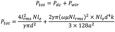
For a winding made with flat conductors, the relation takes the form:
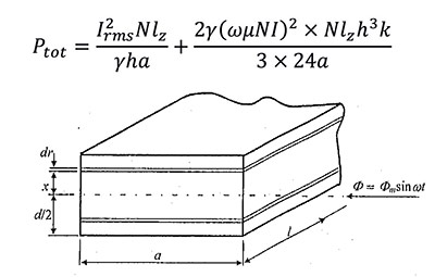
Fig.6 A flat wire placed in a sinusoidal magnetic field. [2]
Correct determination of start values in the windings of power electronic chokes is difficult due to the existence of a wide spectrum of harmonic currents in the circuit, which results in a distortion of the current waveform. In such a case, the harmonic components should be extracted by decomposing the current waveform into a Fourier series and the resistance factor for each significant current component should be determined separately. In core chokes, an additional and dominant component of winding losses are eddy current losses associated with the effects of scatter flux around air gaps in the core [3,4]. Reducing this part of the loss is possible by using the CoreECOTM multi-slit core technology, which reduces the dispersion of magnetic induction in the space around the core [3,6].
The skin effect
When the alternating current i(t) flows in the winding, an alternating magnetic field is generated inside and outside the conductors, which, according to Lentz’s rule, induces eddy currents in the conductor with the direction of flow opposite to the main winding current. Induced eddy currents generate their own magnetic field, which causes the main field to be displaced from the centre of the conductor [1,2,3].
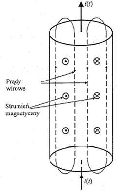
Fig.2 Illustration of eddy currents in a conductor with circular cross section[2]
This leads to an uneven current distribution across the conductor cross-section. The highest current density occurs near the surface and the lowest in the axis of the conductor. This means that the effective, conductive cross-sectional area of the conductor is smaller than the actual physical area. This phenomenon is called the skin effect.
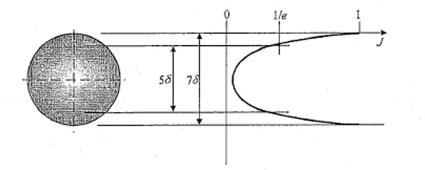
Fig.3 Illustration of the depth of current penetration in a wire with circular cross-section. [2]
The intensity of the skin effect increases with increasing current frequency in the winding. The high-frequency components of the current in the choke windings flow through the surface layer of the conductor cross-section, increasing the current density in this area. Additional power losses caused by skin effect in conductors are called eddy current losses. The quantity defining the intensity of the phenomenon is the current penetration depth δ:
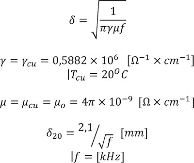
The penetration depth decreases as the specific conductivity of the material γ, or the frequency of the current in the circuit, increases. The smaller the current penetration depth, the higher the resistance of the conductor. The winding resistance increase factor taking into account the skin effect in a circular conductor of diameter d is:

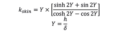
For flat conductors of h dimension for any current frequency, the relation for the resistance factor takes the form [2]:
References
[1]. Alex Van den Bossche, Vencislav Cekov Valchev” Inductors and Transformers for Power Electronics”, Taylor & Francis Group, 2005.
[2]. K. Rumatowski, “Straty mocy w uzwojeniach transformatorów zasilaczy impulsowych”, WPP, Poznań 2002.
[3]. Kazimierczuk M.K.”High-frequency magnetic components,” 2009 A John Wiley and Sons, Ltd.
[4]. A. Stadler, R. Huber, T. Stolzke, C. Gulden “Analytical Calculation of Copper Losses in Litz-Wire Windings of Gapped Inductors”, IEEE TRANSACTIONS ON MAGNETICS, VOL. 50, NO. 2, FEBRUARY 2014
[5]. A. Młot, M. Łukaniszyn, M. Korkosz “Wpływ efektu zbliżeniowego i naskórkowości na straty mocy w uzwojeniu silnika elektycznego” Zeszyty problemowe – Maszyny Elektryczne Nr 100/2013 cz. I
[6]. M. Łukiewski “Dławiki układów napędowych z rdzeniami w technologii wieloszczelinowej CoreECO” Urządzenia dla Energetyki 3/2019
Download PDF
M. Łukiewski – Urządzenia dla Energetyki 4/2019