Drive system chokes operating at the inverter output are exposed to harmonic voltages and currents. Such operating conditions encourage significant additional losses. The use of the best magnetic materials and new technological and design solutions in chokes determines their technical parameters and durability. TRAFECO Sp. J. is a manufacturer of low-loss chokes dedicated to operate in drive systems.
Effects of voltage inverters
The controlled drive systems are powered by voltage inverters with Pulse Width Modulation (PWM) output. Such circuits can operate at increasing switching frequencies and high steepness of du/dt voltage pulses. This is the cause of a number of parasitic phenomena in motors. Overvoltage at the motor terminals, increased losses and noise are phenomena that shorten motor life and reduce efficiency [1, 2].
Limiting the influence of the distorted voltage on the motor and the cable line is achieved by using — at the converter output — motor chokes type 3RTM or du/dt chokes type 3RTU. The motor and du/dt choke partially compensate for the cable capacitance and mitigate the steep rise in du/dt voltage pulses, which protects the motor and cable insulation system. In the inductive components working at the output of the converter, additional losses arise as in the motor. The multiplicity of additional losses occurring in the core and winding of a choke depends on its design and the technological solutions applied. Wide gaps in the choke core cause magnetic flux dissipation which is a direct cause of additional losses in the core [4, 5].
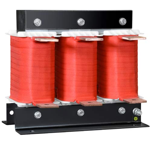
Figure 1. 3RTM low loss motor choke with CorECOTM multi-slot technology core to reduce losses.
CoreECOTM multi-slot core technology
The classic choke core is constructed from packages of anisotropic transformer sheets. The design of the core assumes that there are several wide air gaps between the blocks of magnetic material in each column. The structural elements of the core, such as angles and pins, are made of ferromagnetic metal. Due to the type of materials used in the construction of the choke, hysteresis losses occur in the ferromagnetic elements and eddy current losses occur in all conductive elements of the choke. The intensity of the basic losses occurring in the choke core depends on the amplitudes and frequencies of the harmonic currents occurring in the circuit and the value of the maximum induction in the core. Eddy current losses also strongly depend on the thickness of the magnetic sheets and the direction of the magnetic flux in the core. The amount of hysteresis loss depends on the lossiness of the magnetic material used.
Continuous magnetic core — the magneto coil concentrates the magnetic flux generated by the choke windings and stabilises its direction. The magnetic core is usually bundled or rolled from sheets as thin as possible in the flux direction. This allows for low losses when the direction of the flux in the core is known and predictable. Discontinuities in the choke cores in the form of transverse column air gaps also occur. Wide air gaps in the core cause a diversion of the stream in the near-slit areas and induce an external scattering stream. The change in flux direction causes an increase in hysteresis fundamental losses due to the anisotropy of the core material and a strong increase in eddy current losses in the core. The range of influence of the magnetic scattering flux depends on the value of induction in the core and the width of the air gaps. The dissipation flux causes eddy current additional losses in the winding and additional eddy current and hysteresis losses in the ferromagnetic metallic structural parts of the choke.
The reduction of hysteresis losses in the core is realized by using transformer silicon sheets with reduced loss or amorphous and nanocrystalline magnetic materials with a very narrow bandwidth of the hysteresis. In the multi-slit core design (Fig.2), the reduction of the scattering flux range around the air gaps is achieved by limiting the width of a single slot in the core. The wide air gap is replaced by several or more narrow slots that reduce the deformation of the flux path in the core and reduce the scatter flux in the space around the core.
In a choke winding where harmonic currents of relatively high frequencies flow, a skin effect and proximity effect occur. These phenomena have a significant impact on the value of losses in the windings of chokes and their understanding allows the correct planning of the cable layout. The skin effect induces current flow only in the surface layer of the conductors and the thickness of the conductive layer decreases with increasing frequency.
The skin effect is reduced by using windings wound with a bundle of parallel insulated wires. The cross-section of a single wire in a bundle is defined according to the depth of current penetration at the surface of the wire. The depth of current penetration depends on the frequency, magnetic permeability and conductivity of the conductor.
Magnetic and magnetostrictive forces occur in a periodically remagnetised magnetic core. The magnitude of the magnetic and magnetostrictive forces depends on the maximum local magnetic induction values in the core. The acting forces induce varying stresses in the core sheets, resulting in vibration of the structural components and an acoustic field around the choke. CorECOTM is a low-loss technology for assembling and bundling multi- slot choke cores, which enables a drastic reduction of a start in the core while reducing the intensity of the acoustic field around the choke [5].
Table 1. summarises the technical parameters of a 30 kW motor choke made using classic and low-loss CorECOTM core-packing technology. The choke winding is also designed to limit the additional losses due to current harmonics. Thanks to complex technological measures to reduce losses, the reduction in total losses of the choke reaches 30%.
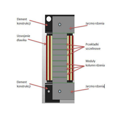
Figure 2. Cross-section of a core column with CorECOTM multi-slot technology to reduce choke losses.
Download PDF
M. Łukiewski – Urządzenia dla Energetyki 3/2019