The rectifier operating in the inverter input circuit draws a highly distorted current from the mains. This causes increased losses in power transformers and in some cases secondarily causes distortion of the supply voltage sinusoid. Partial reduction of current distortion is achieved, among other things, through the use of network chokes.
This paper presents the performance of input chokes used in inverter drive systems. Issues related to the tasks and design of core chokes are discussed.
Tasks of inductive components in a drive system.
The power supply of drive systems by means of converters with Pulse Width Modulation (PWM) at high keying frequencies and high steepness of du/dt voltage pulses causes a number of parasitic phenomena in power cables and motors. Adverse impacts also occur on the mains side. Most inverters are built in a topology with a six-pulse rectifier at the input. This design causes a strong distortion of the current drawn from the grid by the inverter. The current drawn by a six-pulse rectifier is the sum of the harmonic currents of which the fifth harmonic is dominant. The amplitudes of all the current harmonics drawn by the rectifier depend on the grid impedance at the point where the rectifier is connected to the grid. Current harmonics have a detrimental effect on mains power transformers, increasing their losses and secondarily causing a distortion of the supply voltage sinusoid [1].
Partial reduction of the converter’s influence on the mains can be achieved by using a series mains choke in the converter’s supply path. Mains chokes increase the impedance of the mains by reducing the amplitude of harmonic currents drawn from the mains by the rectifiers. By using a choke, we can reduce the value of the current harmonic content factor THDi to a value of approximately 35%. Further reduction of the harmonic content in the current drawn from the grid is possible using higher harmonic filters such as the ThdECOTM type [2].
In thyristor systems commutation chokes with high inductance of 5 – 8%. they reduce the effects of commutation breakdowns and reduce secondary commutation overvoltages. A choke with high inductance is an energy store in a magnetic field. It gives up stored energy during commutation without allowing or limiting the depth of voltage collapse. In contrast to commutation chokes, mains chokes have predominantly lower inductance on which there is about 2 – 4% voltage drop during nominal current flow.
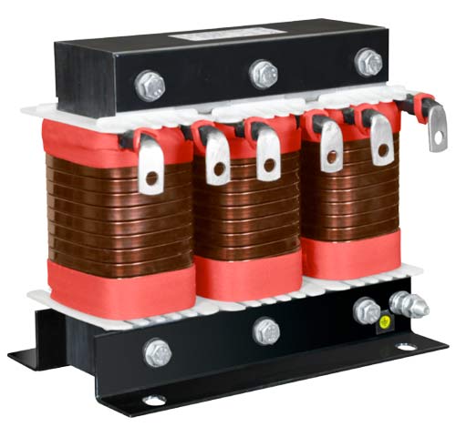
Fig. 2 Three-phase network choke, 3RTN-2% type
Design and parameters of input chokes
Choke losses depend strongly on the harmonic content of the choke current. During the calculations it is extremely important to correctly determine the harmonic spectrum of the current in the choke circuit and the amplitudes of these harmonics according to the actual operating conditions. Only if the real shape of voltage and current is adopted for the design, the choke will work correctly, achieve the assumed temperatures and the calculated losses will be confirmed during operation.
In a choke winding where harmonic currents of relatively high frequencies flow, a skin effect occurs. as well as proximity effect . These phenomena have , a significant impact on the value of losses in the windings of chokes and their understanding allows the correct planning of the cable layout. The skin effect induces current flow only in the surface layer of the conductors and the thickness of the conductive layer decreases with increasing frequency. The skin effect is reduced by using windings wound with a bundle of parallel insulated wires. The cross-section of a single wire in a bundle is defined according to the depth of current penetration at the surface of the wire. The current penetration depth (1) depends on the frequency (f), magnetic permeability (μ, μO,μr) and conductivity (σ) of the conductor [3].
The losses in the magnetic core of the choke consist of the basic hysteresis and eddy current losses and additional losses related to the scattering flux, occurring mainly in areas of discontinuity in the core. Reducing eddy current losses by bundling the core with thin insulated sheets in the case of chokes is insufficient. In the gap areas, there is a change in the direction of the flux, which generates additional eddy current losses in the core material, the winding and in the conductive components.
Magnetic and magnetostrictive forces occur in a periodically remagnetised magnetic core. The magnitude of the magnetic and magnetostrictive forces depends on the maximum local magnetic induction values in the core. The acting forces induce varying stresses in the core sheets, resulting in vibration of the structural components and an acoustic field around the choke.
The choke winding is also designed to limit the additional losses due to occurrence of skin effect. Thanks to complex technological measures to reduce losses, the reduction in total losses of the choke can reach up to 30- 40%.
TRAFECO Sp. J. apart from high quality network and commutation chokes, also manufactures non-standard inductive components, individually designed to individual specifications, dedicated to work in specific and harsh operating conditions.
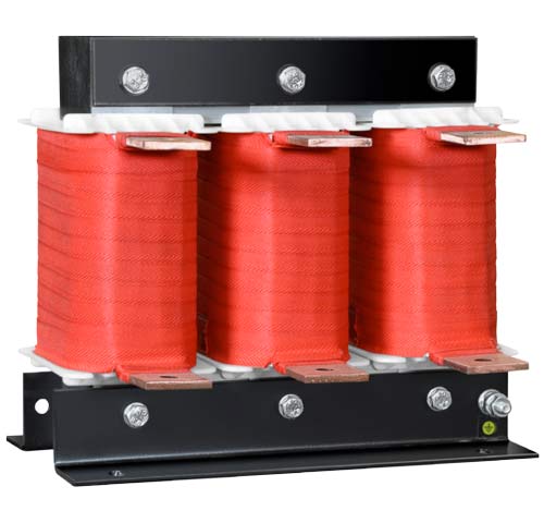
Fig. 1 Three-phase commutation choke, 3RTN – 8% type