Modern inductive components made by TRAFECO for power electronics are built using low-loss magnetic materials and CoreECOTM technology to further reduce losses. This paper presents the performance and design parameters of smoothing, saturation and equalizing chokes and chokes operating in high frequency variable component applications.
Smoothing chokes
The result of the rectifier, in general, is a waveform which is the sum of the constant component and the alternating waveforms of voltage and current. The ripple in the rectified waveform caused by the presence of variable
components in the voltage and current causes additional losses and specific technical problems. The use of inductive elements at the output of the rectifier limits the amplitudes of the variable components of voltage and current giving the effect of smoothing the ripples of the output waveforms. The current in a rectifier circuit often has an impulsive, intermittent waveform. The use of an energy storage choke with sufficiently high inductance makes it possible to restore the continuity of the current flow. The effectiveness of the inductive filter, is the greater the higher the frequency of the variable components of the voltage [1].
Smoothing inductive elements come in three main varieties that differ significantly in the linearity of the magnetic characteristic L(I). Full magnetic linearity is observed in coreless inductive elements of the AirECOTM type. These are so-called air coils, consisting solely of copper or aluminium windings and components. The coils can be adapted for natural or forced air cooling.
Another group are open-core chokes, in which the magnetic flux of the choke is partially enclosed by the surroundings and air. These chokes have a characteristic that is subject to gradual saturation, where it is difficult to determine a specific saturation point or a point of distinct refraction of the L(I) characteristic. The risk of dangerous saturation of this type of choke during overload is very low.
The most common applications are for chokes with a closed sheathed or columnar core.
The characteristics of closed magneto chokes tend to saturate rapidly. The way to control this phenomenon is to introduce high reluctance slots into the magnetic circuit. In the columns of the choke core, several to dozens of air gaps are made, with suitably defined widths, spaced as evenly as possible over the height of the column. This allows you to control and modify the shape of the magnetic characteristic of the choke and the range of its linearity. The effect of shaping the characteristics is the ability to design chokes that will have the required inductances at a given load. This allows us to design and make inductive components that will go into a magnetic saturation state at the appropriate current value.
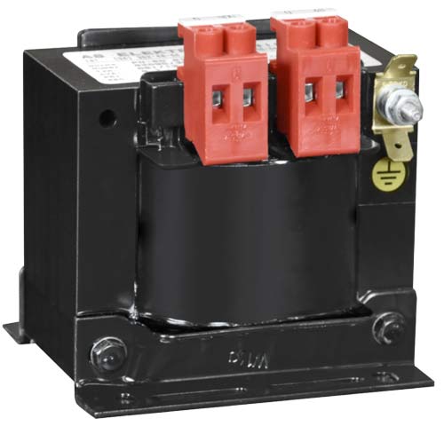
Figure 1. Single-phase smoothing choke, 1RTS type
Design and parameters of pulse control chokes
Direct Current Converters – switches and choppers are used to regulate the average voltage value. The voltage control effect is obtained by controlling the thyristor conduction time at a constant waveform period or by varying the switching frequency at a constant conduction time. Such regulation is used, among others, in DC drives. Current pulsations at the output of the chopper are reduced by using an inductive or inductive-capacitive filter. Such systems operate at a relatively high switching frequency, which is beneficial for the drive, but significantly degrades the operating conditions of the inductive elements in the filter.
Chokes working in output filters of DC choppers are elements exposed to the high frequency component of the current. The DC component of the output current causes sub-magnetisation of the core, while the high frequency AC component is the main source of losses in the core and choke windings. The losses in inductive components depend very strongly on the frequency of the alternating component of the current and on its amplitude defined in amperes of the peak-to-peak value (Ap-p). In a choke winding in which a current of relatively high frequency, there is a skin effect as well as proximity effect . These phenomena often determine the value of losses in the choke winding. The skin effect induces current flow only in the surface layer of the conductors and the thickness of the conductive layer decreases with increasing frequency. The skin effect is reduced by using windings wound with a bundle of parallel insulated wires or thin sheets. The cross-section of a single wire or a sheet thickness in a bundle is defined according to the depth of current penetration at the surface of the wire. The current penetration depth (1) depends on the frequency (f), magnetic permeability (μ, μO,μr) and conductivity (σ) of the conductor [4].
The losses in the magnetic core of the choke consist of the basic hysteresis and eddy current losses and additional leakage losses related to the scattering flux, occurring strongly in areas of discontinuity in the core. Reducing eddy current losses by bundling the core with thin, insulated transformer sheets or using modern, low-loss amorphous and nanocrystalline magnetics for chokes is not sufficient [Table 1]. In the gap areas, there is a change in the direction of the flux, which generates additional eddy current losses in the core material, the winding and in the conductive components.
Equalisation and saturation chokes
Power electronic parallel systems for complex rectifiers (e.g. 12-pulse rectifiers) provide for the use of compensating inductive elements at the connection points between the rectifiers. The purpose of the coupled chokes is to balance the load between the rectifier sections. A similar task is performed by equalizing chokes used in high-power thyristor circuits where thyristors are operated in parallel. The purpose of the choke is to maintain an even current flow in the parallel connected thyristors. Due to the uneven voltage distribution across the thyristors, one of the thyristors will go into conduction sooner. This creates an electromotive force in the choke that counteracts the voltage on this thyristor and simultaneously increases the voltage on the other thyristor. In this way, the coupled choke balances the voltage distribution across the thyristors and results in an equal current load.
The transition to the conduction state of thyristors is gradual. If the thyristor conduction current rises too fast, it may lead to a thermal fault. The reason for this hazard is the finite rate of enlargement of the interface involved in conduction. The use of a saturation choke makes it possible to limit the rate of current rise to a value at least equal to the rate of increase of the surface area of the conducting junction. The choke characteristic is shaped in such a way that it becomes saturated after the introduction of a current rise delay. The choke in this circuit acts as a protection for the thyristor [3].
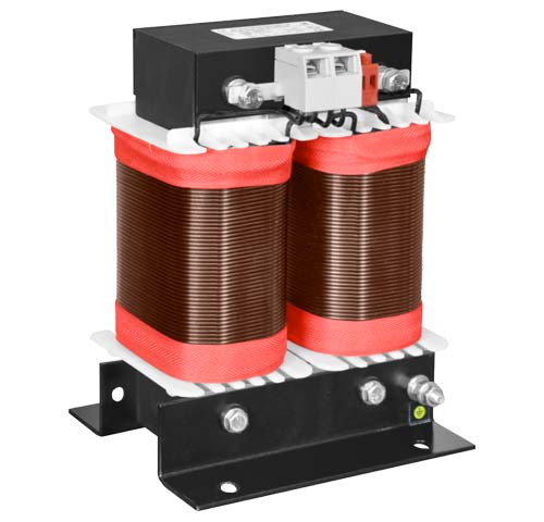
Figure 3. Single-phase chopper choke, 2RTF type
CoreECOTM core production technology
Power losses in power electronic choke depend strongly on the amplitudes and frequencies of the choke current components. The magnitude of power losses in chokes is equally strongly determined by the design of the core and windings. The lack of continuity of the core in the choke is the reason for the occurrence of slotted magnetic scatter flux. This flux causes additional eddy current and hysteresis losses in the choke components and winding.
The range of influence of the near-slit scattering flux depends mainly on the width of the air gaps used in the core [5]. In the case of wide gaps in the core, magnetic coupling of the scattering flux with ferromagnetic structures in the immediate vicinity of the choke can occur. Such inductive losses generated in nearby ferromagnetic components will increase the load current of the choke.
A typical choke core design involves the introduction of several air gaps into the magnetic circuit. The core is usually made of cut pieces of low-loss transformer sheet metal with as little sheet metal thickness as possible in the flux direction. This reduces hysteresis and eddy current losses.
In the case of power electronics chokes of higher power, harmonic filter chokes, where an important technical parameter is the linearity of magnetic characteristics L(I), the construction of the core assumes the existence of wide air gaps allowing to shape the characteristics of the choke. The different parts of the magnetic core material operate under different conditions. This is due to the uneven distribution of induction in the core and the disturbed flux direction. In the cores built of anisotropic transformer sheets we want to shape the course of the magnetic flux in the direction parallel to the rolling direction (the best properties of the sheet), which allows to achieve the lowest hysteresis losses. Modern materials of amorphous or nanocrystalline structure used in chokes for power electronics (Fig.3) are mostly isotropic and a change of the flux direction will not cause an increase in hysteresis losses. Flux direction disturbances in the core, however, will strongly increase eddy current losses in coiled cores made of thin amorphous strips or cores bundled from crystalline sheets, regardless of the thickness of the sheet used.
In the slit areas, there is an unfavourable curvature of the flux direction in the core, which by penetrating almost perpendicularly, wide plates generates intense additional eddy current losses in the core material.
Download PDF
M. Łukiewski – Urządzenia dla Energetyki 5/2018